

What operator type do you have?
What Board are you having trouble with?
What board are you having trouble with?
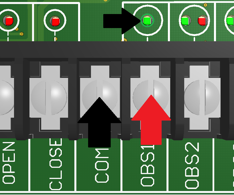
Connect the pulse monitored photo eyes included with the unit to OBS1 and COM
Ensure that your Omron Photo Eyes are monitored
Connect terminal 1 on the Omron to OBS2 on Turbo, and terminal 2 on the Omron to COM on Turbo
Connect the power terminals on the Omron to ILK and COM on Turbo

Ensure monitored photo eyes are connected to OBS1 and COM and that the OBS1 status light is solid GREEN
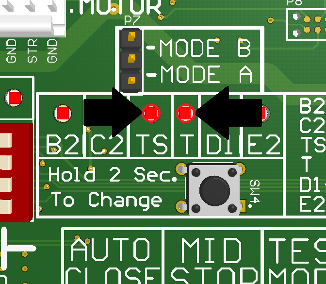
Set board to either T or TS operation mode
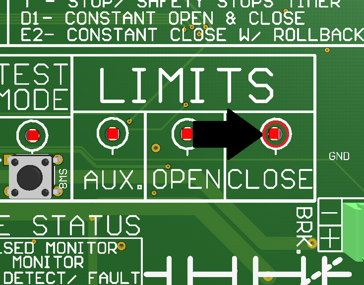
Close the door and ensure the CLOSE LIMIT status light is solid RED
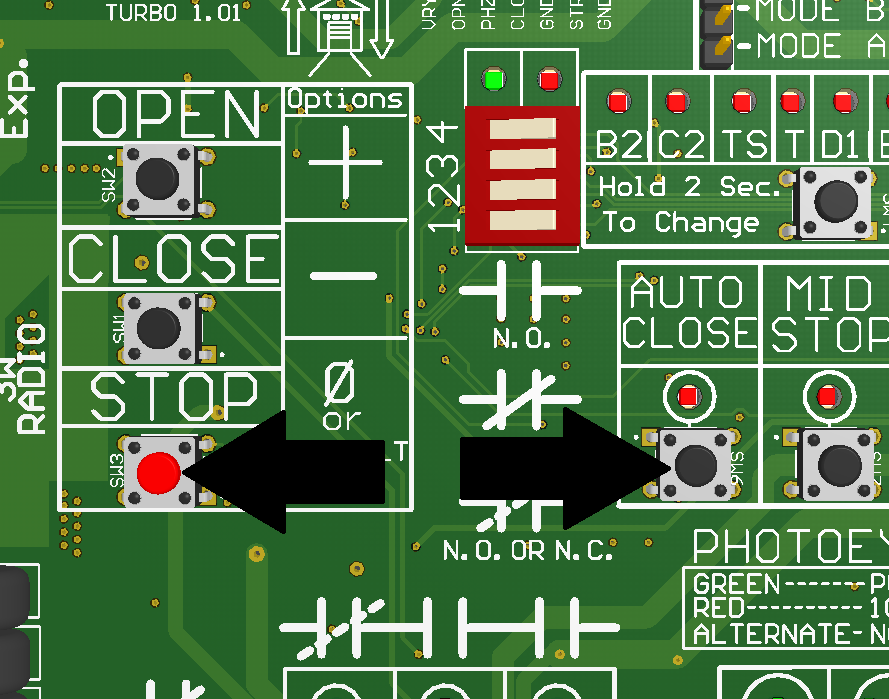
Hold the STOP and AUTO CLOSE buttons for 3 seconds to reset the timer
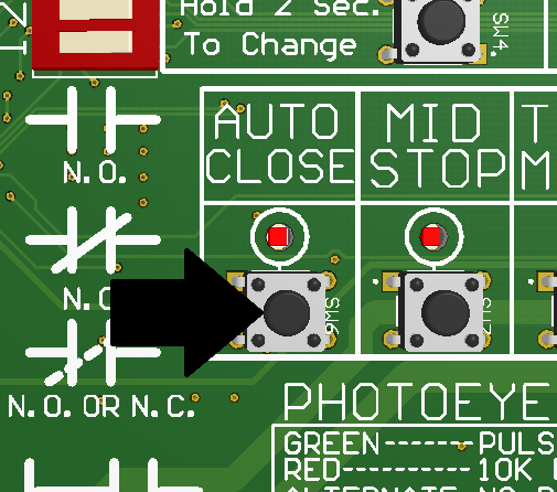
Press the AUTO CLOSE button one time for every five seconds you would like added to the timer
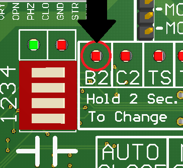
Is the operator on B2?
Change operation mode to B2

Are monitored photo eyes on OBS1 and COM?
Connect monitored photo eyes to OBS1 and COM
Reset the Turbo Board
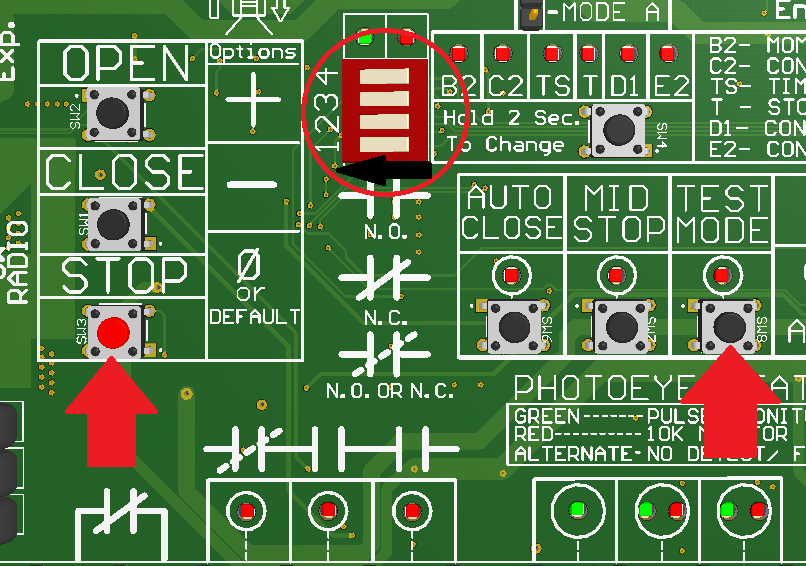
To restore factory settings, turn all four dip switches to the ON position and hold TEST MODE and STOP buttons until all LEDs are off.
Disengage hand chain
Put interlock connector on NC
Replace interlock switch
Does the board power on?
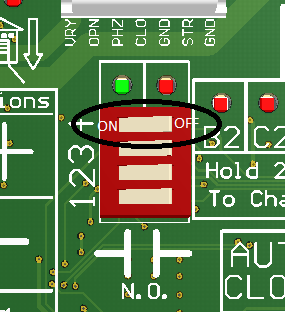
If DIP Switch #4 is on, turn it off
Is the red LED above STOP on?
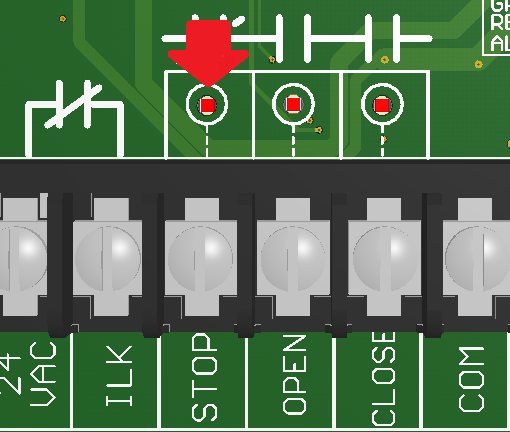
Place a jumper between STOP and COM
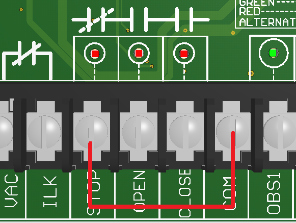
Does the light turn off?
Replace the 3-Button Wall Station
Is the red LED above STOP still on?
Please call Power Master Technical Support and give Error Code
Are either of your limit switches engaged?
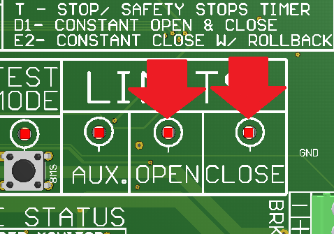
Manually move your door to a point of mid travel
Are there any indicator lights on?
Disconnect any components from the indicated terminals
What is the voltage across the first 24VAC and ILK?
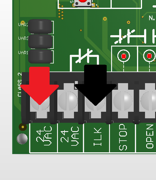
Please call Power Master Technical Support and give Error Code
Is the hand chain switch engaged?
What is the voltage across 24VAC and 24VAC

Is the interlock switch connection on NC?
Check Voltage across L1 and L2
Please call Power Master Technical Support and give Error Code
Improper incoming voltage, use a different dedicated power source.
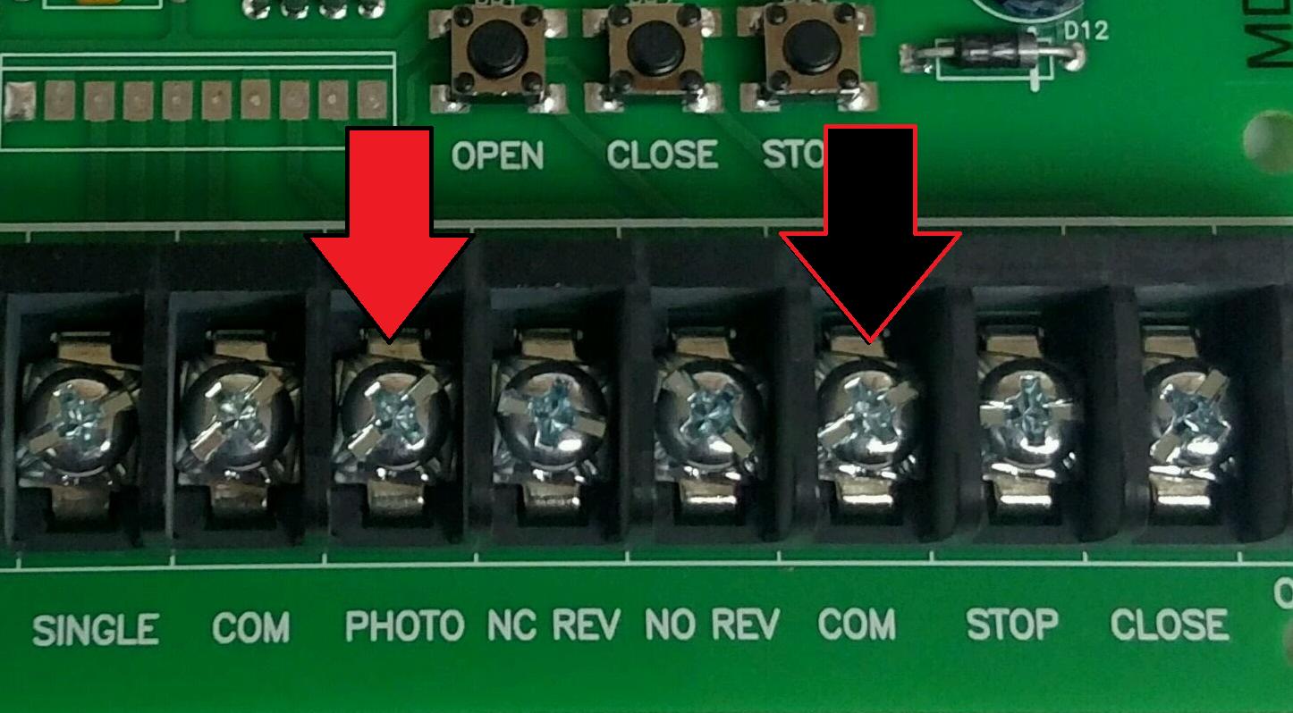
Ensure monitored photo eyes are connected to PHOTO and COM
Run door to close limit
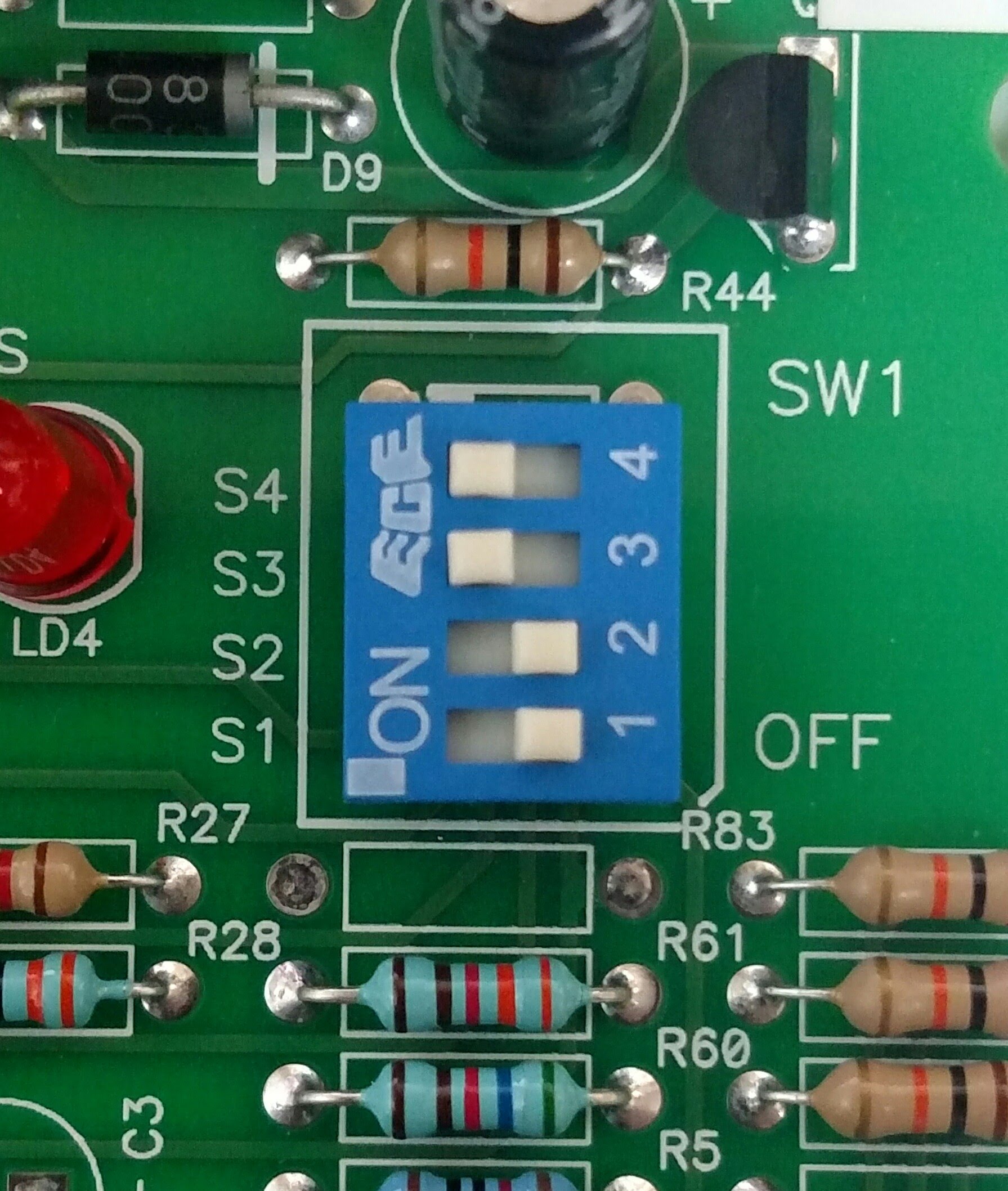
Set dip switches on the board to the following configurationSwitch 4-ONSwitch 3-ONSwitch 2-OFFSwitch 1-OFF
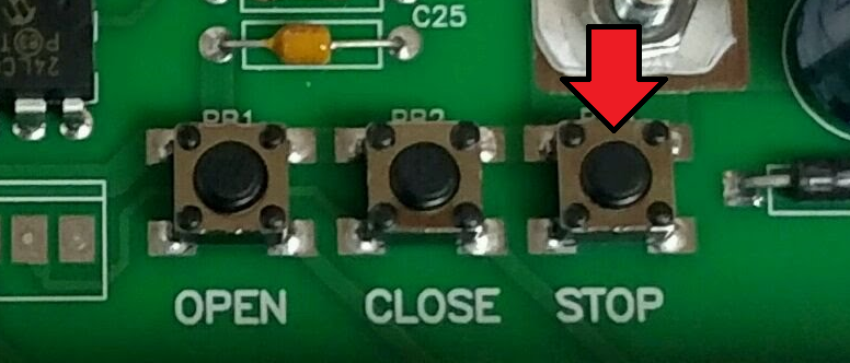
Press the STOP button to clear the Auto Close Timer
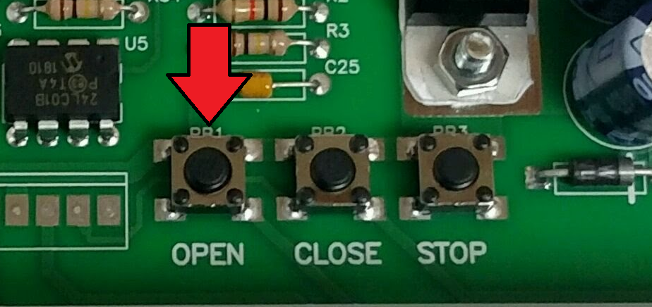
Press the OPEN button to add 5 seconds to the Auto Close Timer
Set the dip switches to operating mode T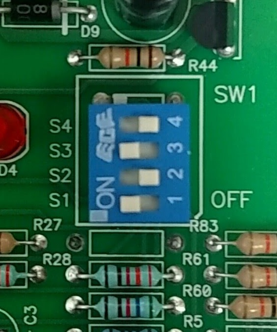 Switch 4-OffSwitch 3-OnSwitch 2-OffSwitch1-On
Or operating mode TS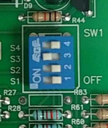 Switch 4-OffSwitch 3-OnSwitch 2-Off
Switch 1-Off
What is the voltage across the 24VAC and ILK terminals?
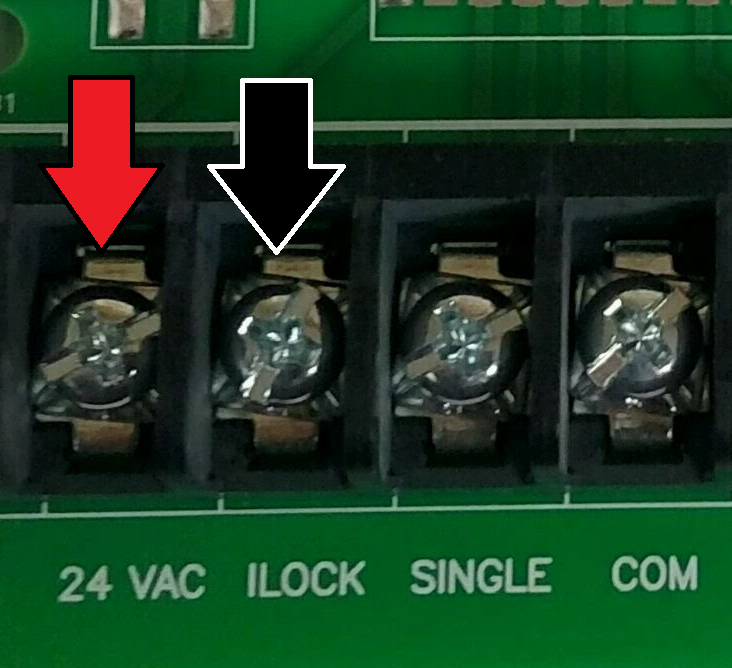
Please call Power Master Technical Support and give Error Code
Is the hand chain switch engaged?
Disengage hand chain and try to run the operator
Does the board power on?
Place a jumper between STOP and COM and try to run operator
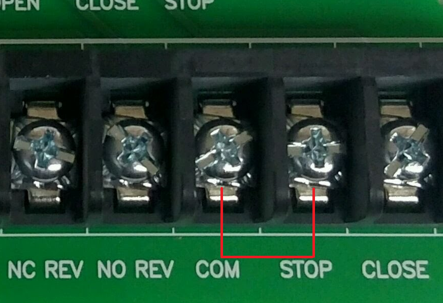
Does the operator run?
Replace the 3-Button Wall Station
Does the Red LED blink when the board is powered on?
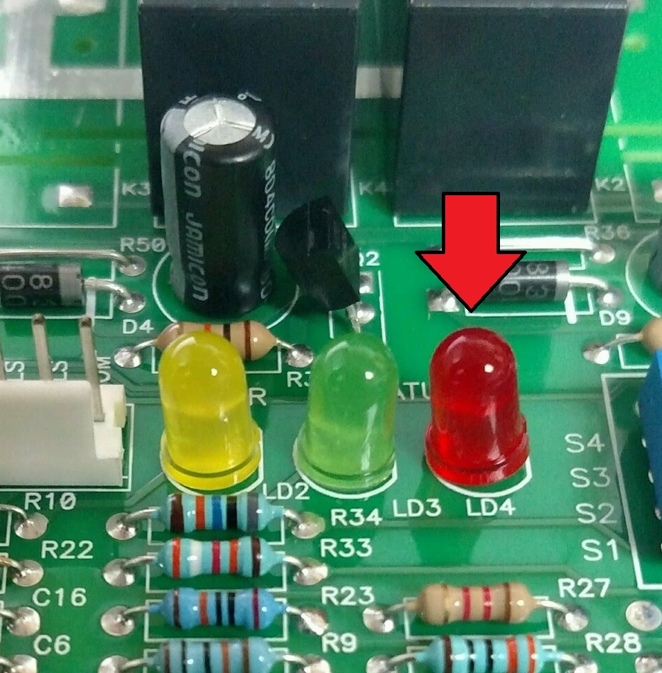
Please call Power Master Technical Support and give Error Code
Manually move door to a point of mid travel
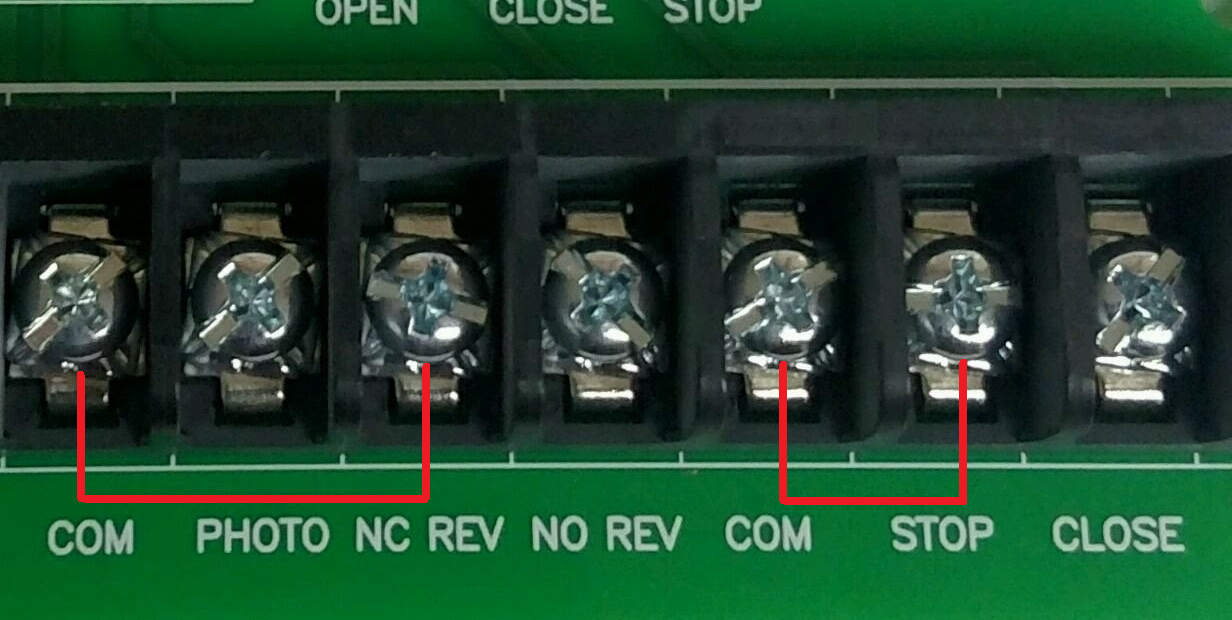
Disconnect any accessories from board except for the jumper between STOP and COM and place another jumper between NC REV and COM
Does the operator run?
Please call Power Master Technical Support and give Error Code
Reconnect accessories 1 by 1 and attempt to run operator to determine which accessory is causing the error.
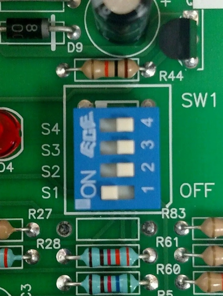
Is the operator on setting B2?
Change operation mode to B2

Are monitored photo eyes on PHOTO and COM?

Connect monitored photo eyes to PHOTO and COM
Reset the CDO Board

To restore board to factory settings:-Remove power from the board-Press and hold the on-board stop button-restore power to the board while holding down the on-board stop button
Are there monitored safeties in the OPEN and CLOSE directions?
Reset Resi Board by cycling power while holding both limit switches.
Connect Monitored safeties to the OPEN and CLOSE safeties.
Replace the circuit board.
If you're still having problems, call Power Master Tech Support
If you're still having problems, call Power Master Tech Support
Great! Have a nice day!
Did that fix your problem?